
January 19, 2017
This is the first school project I’ve blogged about. For our project course at school we are making a haptic interface. A haptic interface is a system that responds to physical human body movement, and produces computer simulated tactile feedback. Apparently our prof for this course used to work on control systems for surgical robotics, and the haptic interface he was working on for it provided feedback that made the user feel gross whenever they made cuts and incisions. Haptic interfaces also have a lot of applications for virtual reality. Our group hasn’t really decided what practical application we’ll do with ours yet.
In second year we made a pretty cool remote-controlled robot car, and I felt it was kinda sad that I just sorta forgot about it. We have to do a report on this project anyways, so I thought I might as well write as we go and keep these posts as a memoir.
So far we are working on a haptic interface for a linear actuator - the user will be able to move the linear actuator up to a certain threshold, at which point the haptic interface will simulate hitting a physical boundary. We’re trying to make the feedback from the boundary make the user feel as if he/she were pushing on a spring. We’re working on one degree of freedom for now, but eventually we’ll expand to at least two degrees of freedom.
The linear actuator will contain a linear motor, which will be inactive until the the user approaches the boundary. The motor will turn on to oppose the direction the user is pushing when this happens, then, as the user continues to push against the boundary, the torque of the motor will increase. This is to simulate the feeling of pushing against a spring. So far we are using a rotary encoder to measure the distance the user has moved.
We were told to split our team of four into two - two people working on making the custom motor, and two people working on the real time programming and control systems. A friend and I are the latter group.
While we wait for the motors group to build a linear motor, us control systems folk have been working with a store-bought motor and rotary encoder meanwhile to get started on the real time programming and circuitry.
We’ve been using an L298N chip as an H-bridge for our 12V commercial motor. We based our driver circuit off of figure 6 from its datasheet:
We didn’t bother with a pull down resistor though. We just put in a jumper to ground that pin, and figured that the wire would have enough resistance. If you put a pull-down resistor there that is too high, the circuit won’t drive your motor. We also used standard schottky diodes instead of fast recovery diodes, since we didn’t really have any better diodes around.
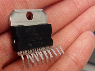
We actually spent hours trying to troubleshoot why this seemingly simple circuit wouldn’t work for us right away. In the end, we found out that it was because we had not pushed the legs of the IC into the breadboard far enough to touch the multiclips… d’Oh. If you look here, the legs of the L298N aren’t meant for the standard breadboard:

When we probed the output pins with a multimeter, we constantly got around 0V and couldn’t figure out why :(. After hours of taking about the circuit and rebuilding it, thinking we had made a mistake in wiring, my partner suggested that maybe the chip wasn’t inserted into the board properly. Nonsense, how could we mess up such a trivial thing? We tried reconnecting the legs of the IC to the breadboard with female-male jumpers anyways, since we had no better ideas by that point. Still, the output pins probed 0V… We had run out of ideas after that, so I got the motor working with an sn754410 meanwhile so we’d at least have the motor working with SOME IC meanwhile, so we could move on to other things. After the weekend, out of ideas and heartbroken, my partner suggested the chip we were using was fried while we tried powering it when it wasn’t connected properly. So she swapped the chip with a new one and…everything worked -_-. Just a day in the life of hardware, I guess.
The two motor IC’s are pretty similar, except L298N can run at a max of 2A (sn754410 can only run at a max of 1A) and has a built-in heat sink. But our motors people will need up to 4A for the custom made motor we just find out, so we’ll either have to look into a higher current H-bridge IC or wire the L298N in parallel to handle 4A. I’m a bit sketched out by the latter proposition, since the current might be distributed unevenly. I still have to look into this.
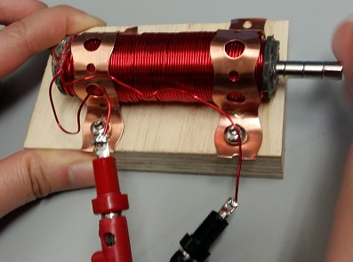
Their custom made motor is looking pretty great, on another note:

To be continued…