
The workspace for our haptic interface arm was really small, so it was hard to tell what the arm was drawing when moving autonomously, or for the user to tell what was going on when he/she was moving around the effector. I had D3 plot the position of the effector as it was moving around, so we could clearly demonstrate the precision with which our control system was drawing. It also came in handy for testing out our math, and testing in general, to make sure we were actually drawing shapes and performing desired movement, and not just watching/feeling the effector move around doing diddly squat.
Here’s an old video of us testing out the real time plotting (I know it’s dark, but look at the top right to see the arm moving around):
Here is an early screenshot of the something the arm drew that the D3 plot captured:
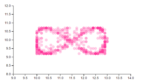
Ignore the scale - I had a scaling factor making it proportionally too large in either direction in the math at first. As you can see, the density of dots reflects the most frequent positions of the effector. You’ll notice some faint pink dots - early on, the effector had a bit of shake to it. The faint pink dots which strayed from the desired path indicated that we needed to tune our system more.
Here is a screenshot of a more finely tuned design:
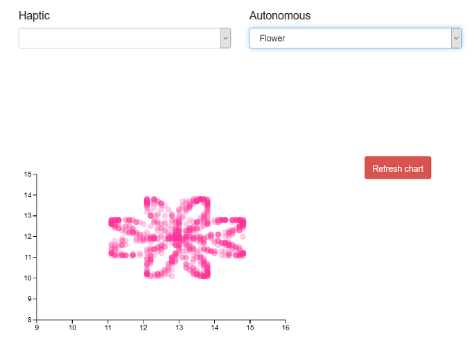
I guess the sin function we used could have used a vertical scaling factor a tad bit larger, but notice that the system in this plot had much steadier control.
We had the dots drawn in dark blue as the effector reached each position, then used an animation to fade them purple, then to pink. These screenshots were taken after the whole animation had faded to pink.
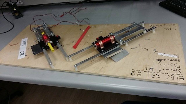
I couldn’t find much on real time data visualizations in D3. For the most part, I could only find demos which updated D3 graphs say, every 1-5 seconds. This wasn’t good enough for what we needed. We needed a plot that could instantaneously reflect minute changes of the effector position in our workspace. Unfortunately I am writing this post over 2 months after completing the project, but our workspace was only a few cm long and a few cm wide (maybe 4cm? The scale is wrong in some of the screenshots I took, as early on I had entered the arm length of the robot arm wrong and it increased the scale of everything by a factor…took us like two hours to figure out what was going wrong, har har…). Precision and changes in movement were detected for +/- 0.001cm, if I remember correctly…it may have been even more precise than that. I wish I could just run the thing again and check, but after we demoed the project we ripped it apart to salvage parts. So our project now looks like this:
I may write a tutorial on it later, but this post will summarize what I did to create a D3 plot which plotted movement of the robot arm effector, plotting what it drew on a web application. Along with D3.js I used, Node.js and ExpressJS, the serialPort library on npm, and Socket.io.
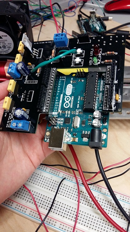
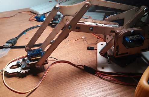
Here’s what the setup of our project looked like:

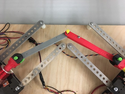
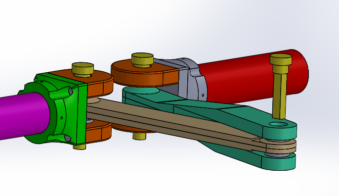
Our project was essentially two linear motors attached to an arm with a joint. As the rotor of the linear motors were moved back and forth, the position of the joint (the effector - the yellow dot in the picture below) would move. We attached a slide potentiometer to each of the linear motors to measure how far in and out they had moved at each given moment based on their readings.
Angled view of arm assembly in AutoCad:
This is a summary of what I did to set up communication with the D3 plot, if you don’t want to read the whole post:
Used Node.js to serve the application off of, used ExpressJS as middleware
Used Socket.io to communicate between the web client and server
Used the serialport library to connect Node.js to my computer’s serial port. Using this library you could write directly to the serial port by writing to the Node.js server (ie through a console.log()), and directly to the Node.js server by writing to the serial port. This latter in my case would be doing Serial.println()’s from the Arduino, for example (Serial.println() was actually too slow for our purposes, but I’ll write more on how we worked around that later).
Used Socket.io to establish communication between the web client and server. We would have the microcontroller take in readings from the two potentiometers, then send the readings to the Node.js server, which would send it to the client through the web socket. At first I had the client do all of our math with the reading values to calculate effector position, as we weren’t that confident in our solution. This way we could move the effector to different positions and view the output on the D3 graph to make sure the output of our calculations was effectively matching our movements
Used D3.js after parsing the string readings to render calculated position value on scatter plot, based on the two potentiometer readings at a given moment. Added in animations for prettiness.
First, we needed a way to communicate between hardware and software. That is, we needed the microcontroller to send information on the effector position to the Node.js server.
There wasn’t tons out there that really supported our needs - Johnny Five has become pretty popular library for using JS to conrol Arduino, Raspberry Pi, and various other hobby microcontrollers. It’s moreso a solution to replace doing your firmware in JS instead of C, however. This wouldn’t work as the rest of my team was familiar with C, and additionally we did not want to slow down our system by using JS. Our control system was extremely time sensitive - it may have been a risk, adding on the compile time of JS. On top of this Johnny Five works by creating objects for different components in your circuit, and then calling functions for those objects. This would limit us to whatever objects the Johnny Five library supported. Sure they have buttons, LED’s and basic sensors, but sometimes we needed very specific components, and didn’t want to run into the problem of them not being supported. For example, the slide potentiometers we were using were exponential, and I don’t think Johnny Five would just happen to have an exponential potentiometer built into the library which perfectly matched the exponential curve and calibration at which ours increased at.
Another problem is that we needed constant bidirectional communication between the hardware and software, and Johnny Five is designed for one way - it is mostly for writing commands to the hardware, and not the other way around.
I chose the serialPort library because we could keep coding for our microcontroller in C, and communicate with the web server by simply writing to the serial port. From the server we could send the received strings from the microcontroller to the client through a web socket.
We sent over the potentiometer readings between start and stop characters so we could define each individual reading and which potentiometer it belonged to. Readings from the left potentiometer were sent as, for example, B1020E, and readings from the right potentiometer were sent as C108E.
After parsing the left and right readings on the client side and then displaying the respective calculated x and y positions on the D3 plot, we could move the effector around and try to draw shapes, and ensure the software was accurately reflecting movement. This was part of our testing process to make sure our math was working. Eventually, we applied math with the potentiometer readings all on the microcontroller in C, then sent the calculatex x and y positions between the start and stop characters.
It got really difficult not messing up the timing of our control system with Serial.println(). These constant prints got expensive, and would mess up the control system and cause the arm to go out of control. This was probably related to the fact that we were using a measly Arduino Uno, which has pretty limited clock speed… not that Arduino Uno isn’t amazing, but near the end of the project we realized how the extra clock speed of an Arduino Mega or some fancier microcontroller would have helped a lot. We couldn’t send our data through interrupts either, as Serial.println()’s in the Arduino Uno interfere with the ISR. I ended up having to write a custom parser with sprintf() (much less expensive) to send over our data through the microcontroller, instead of just using normal prints:
	void write_to_serial(float x, float y){
	      char xStr[6];
	      if( x < 10){
	        char xBuffer[1];
	        dtostrf(x,2,3,xBuffer);
	        sprintf(xStr, "%c%c%c%c%c", beginR, xBuffer[0],xBuffer[1],xBuffer[2],endR);
	      }
	      else{
	        char xBuffer[2];
	        dtostrf(x,2,3,xBuffer);
	        sprintf(xStr, "%c%c%c%c%c%c", beginR, xBuffer[0],xBuffer[1],xBuffer[2],xBuffer[3],endR);
	      }
	      Serial.write(xStr);

	      char yStr[6];
	      if( y < 10){
	        char yBuffer[1];
	        dtostrf(y,2,3,yBuffer);
	        sprintf(yStr, "%c%c%c%c%c", beginL, yBuffer[0],yBuffer[1],yBuffer[2],endL);
	      }
	      else{
	        char yBuffer[2];
	        dtostrf(y,2,3,yBuffer);
	        sprintf(yStr, "%c%c%c%c%c%c", beginL, yBuffer[0],yBuffer[1],yBuffer[2],yBuffer[3],endL);
	      }
	      Serial.write(yStr);
	}
Initially I struggled a lot with getting the client to consistently communicate with the microcontroller. Sometimes it just did nothing and failed silently, and wasn’t receiving or updating the incoming string data. One of the biggest game changers was discovering the parser property when setting up the serialPort on the server. With this property in serialPort library, you can set the end character and have serialPort automatically split your string when it sees it in incoming data. This ENORMOUSLY improved performance. Here are the settings I instantiated serialPort with:
	var port = new SerialPort("COM6", {   //*change this to COM port arduino is on
	       baudrate: 9600,
	       parser: SerialPort.parsers.readline("E"),
	       dataBits: 8,
	       parity: 'none',
	       stopBits: 1,
	       flowControl: false
	  });
And this is the client side parsing we then used:
	socket.on('updatePot', function(data){
	    unParsedData += data;
	    if(unParsedData.charAt(0) === "B"){
	        console.log("in if x:" + unParsedData);
	        rightReading = unParsedData.substring(unParsedData.indexOf('B')+1);
	        console.log("x: " + rightReading);
	        dataset.push([rightReading,leftReading]);
	        unParsedData = ""; //reset string that receives data
	        update(); //update d3 scatterplot
	    }
	    //left potentiometer reading
	    if(unParsedData.charAt(0) === "C"){
	        console.log("in if y:" + unParsedData);
	        leftReading = unParsedData.substring(unParsedData.indexOf('C')+1);
	        console.log("y: " + leftReading);
	        unParsedData = "";
	        dataset.push([rightReading,leftReading]);
	        update(); //update d3 scatterplot
	    }
});I’m hoping I can skip the details and basics of D3 here. Basically, I created the initial scatter plot like this:
	var xAxis = d3.svg.axis()
	    .scale(xScale)
	    .orient("bottom")
	    .ticks(10);

	// Define Y axis
	var yAxis = d3.svg.axis()
	    .scale(yScale)
	    .orient("left")
	    .ticks(10);

	// Create SVG element
	var svg = d3.select("#scatter-plot")  // This is where we put our vis
	    .append("svg")
	    .attr("width", canvas_width)
	    .attr("height", canvas_height)

	// Create Circles
	svg.selectAll("circle")
	    .data(dataset)
	    .enter()
	    .append("circle")  // Add circle svg
	    .attr("cx", function(d) {
	        return xScale(d[0]);  // Circle's X
	    })
	    .attr("cy", function(d) {  // Circle's Y
	        return yScale(d[1]);
	    })
	    .attr("r", 2)
	    .on("mouseover", function(d) {
	            tooltip.transition()
	                .duration(50)
	                .style("opacity", .9);
	            div .html(xScale(d[0]) + "<br/>"  + yScale(d[1]))
	                .style("left", (d3.event.pageX) + "px")
	                .style("top", (d3.event.pageY - 28) + "px");
	            })
	        .on("mouseout", function(d) {
	            tooltip.transition()
	                .duration(50)
	                .style("opacity", 0);
	        });  // radius
The plot would intially start out empty. If you look back up at the client parsing code, you’ll notice it is wrapped in a socket event, which is triggered when new incoming data comes in from the server/microcontroller. Once the new data is parsed, it is pushed to a local array (either the array for the right or left motor’s position), and the update() function is called, which plots the new x,y coordinates on the scatter plot:
	function update() {
	    // Update scale domains
	    xScale.domain([xmin, xmax]);

	    yScale.domain([ymin,ymax]);

	    //render newly added elements of array
	    var dataSelection = svg.selectAll("circle")
	                            .data(dataset);

	    dataSelection.enter()
	        .append("circle")  // Add circle svg
	        .attr("cx", function(d) {
	            return xScale(d[0]);  // Circle's X
	        })
	        .attr("cy", function(d) {  // Circle's Y
	            return yScale(d[1]);
	        })
	        .attr("fill", "blue")
	        .attr("r", 6.5);

	  // Update circles
	    svg.selectAll("circle")
	        .data(dataset)  // Update with new data
	        .transition()  // Transition from old to new
	        .attr("cx", function(d) {
	            return xScale(d[0]);  // Circle's X
	        })
	        .attr("cy", function(d) {
	            return yScale(d[1]);  // Circle's Y
	        })
	        .each("end", function() {  // End animation
	            d3.select(this)  // 'this' means the current element
	            .transition()
	            .duration(500)
	            .attr("fill", "#ff3399")  // Change color
	            .attr("r", 5);  // Change radius
	        });

	    // Update X Axis
	    svg.select(".x.axis")
	        .transition()
	        .duration(1000)
	        .call(xAxis);

	    // Update Y Axis
	    svg.select(".y.axis")
	       .transition()
	       .duration(100)
	       .call(yAxis);
}This is just a quick summary of what we ended up doing for our Haptic Interface project for ELEC 391. I won’t get into the details of how all the hardware was done.
We started out with an unclear idea of what the criteria of the project was supposed to be, I guess. All we understood is that we had to build something with linear motors that provided tactile feedback. Throughout the duration of the semester the professor clarified what he expected, and standards rose based on what others in the class were implementing (part way through the semester we were told we would be marked comparitively, not objectively based on a rubric).
In the end the baseline requirements were:
This is the first school project I’ve blogged about. For our project course at school we are making a haptic interface. A haptic interface is a system that responds to physical human body movement, and produces computer simulated tactile feedback. Apparently our prof for this course used to work on control systems for surgical robotics, and the haptic interface he was working on for it provided feedback that made the user feel gross whenever they made cuts and incisions. Haptic interfaces also have a lot of applications for virtual reality. Our group hasn’t really decided what practical application we’ll do with ours yet.
In second year we made a pretty cool remote-controlled robot car, and I felt it was kinda sad that I just sorta forgot about it. We have to do a report on this project anyways, so I thought I might as well write as we go and keep these posts as a memoir.
So far we are working on a haptic interface for a linear actuator - the user will be able to move the linear actuator up to a certain threshold, at which point the haptic interface will simulate hitting a physical boundary. We’re trying to make the feedback from the boundary make the user feel as if he/she were pushing on a spring. We’re working on one degree of freedom for now, but eventually we’ll expand to at least two degrees of freedom.
The linear actuator will contain a linear motor, which will be inactive until the the user approaches the boundary. The motor will turn on to oppose the direction the user is pushing when this happens, then, as the user continues to push against the boundary, the torque of the motor will increase. This is to simulate the feeling of pushing against a spring. So far we are using a rotary encoder to measure the distance the user has moved.
We were told to split our team of four into two - two people working on making the custom motor, and two people working on the real time programming and control systems. A friend and I are the latter group.
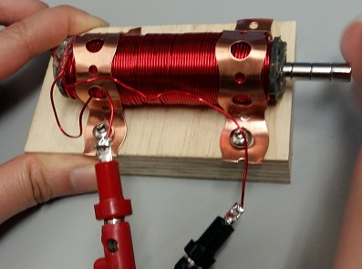
While we wait for the motors group to build a linear motor, us control systems folk have been working with a store-bought motor and rotary encoder meanwhile to get started on the real time programming and circuitry.
We’ve been using an L298N chip as an H-bridge for our 12V commercial motor. We based our driver circuit off of figure 6 from its datasheet:
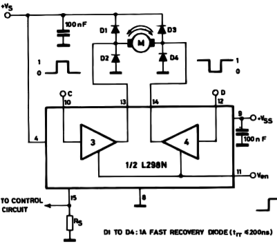
We didn’t bother with a pull down resistor though. We just put in a jumper to ground that pin, and figured that the wire would have enough resistance. If you put a pull-down resistor there that is too high, the circuit won’t drive your motor. We also used standard schottky diodes instead of fast recovery diodes, since we didn’t really have any better diodes around.
We actually spent hours trying to troubleshoot why this seemingly simple circuit wouldn’t work for us right away. In the end, we found out that it was because we had not pushed the legs of the IC into the breadboard far enough to touch the multiclips… d’Oh. If you look here, the legs of the L298N aren’t meant for the standard breadboard:
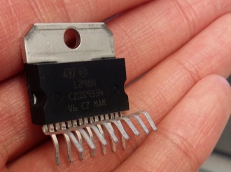
When we probed the output pins with a multimeter, we constantly got around 0V and couldn’t figure out why :(. After hours of taking about the circuit and rebuilding it, thinking we had made a mistake in wiring, my partner suggested that maybe the chip wasn’t inserted into the board properly. Nonsense, how could we mess up such a trivial thing? We tried reconnecting the legs of the IC to the breadboard with female-male jumpers anyways, since we had no better ideas by that point. Still, the output pins probed 0V… We had run out of ideas after that, so I got the motor working with an sn754410 meanwhile so we’d at least have the motor working with SOME IC meanwhile, so we could move on to other things. After the weekend, out of ideas and heartbroken, my partner suggested the chip we were using was fried while we tried powering it when it wasn’t connected properly. So she swapped the chip with a new one and…everything worked -_-. Just a day in the life of hardware, I guess.
The two motor IC’s are pretty similar, except L298N can run at a max of 2A (sn754410 can only run at a max of 1A) and has a built-in heat sink. But our motors people will need up to 4A for the custom made motor we just find out, so we’ll either have to look into a higher current H-bridge IC or wire the L298N in parallel to handle 4A. I’m a bit sketched out by the latter proposition, since the current might be distributed unevenly. I still have to look into this.
Their custom made motor is looking pretty great, on another note:
To be continued…
I made this blog with Jekyll, and have been pretty content with the Jekyll experience, despite making the website while on a Windows PC (Jekyll doesn’t officially support Windows). Jekyll is a parsing engine that handles blogging logic for you, and makes it possible to host a blog on a static site. Removes the hassle of storing posts in a database, etc. Anyhow I just wanted to list a few gotchas to Jekyll in this post - even though Jekyll is pretty great, there are a few things that are just useful to keep in mind to save you some time.
1. Setting up Jekyll on Windows
As mentioned, Jekyll doesn’t officially support Windows. You can get it to work on Windows with a few tweaks anyways though. The official Jekyll documentation does a good job of explaining what you need to do, but I remember installation being a bit fussy for me. Here’s a quick Cole’s Notes style set of instructions for what I did to get it working on my Windows 10 PC eventually:
1) Install Chocolatey.
2) Install Ruby v2.2.4 by running the command choco install ruby -version 2.2.4. If you have a later version of Ruby installed, you MUST uninstall it before you do this. Simply setting the flag to --allow downgrade is not enough.
3) Install the corresponding Ruby development kit with the choco install ruby2.devkit command.
4) Navigate to C:\tools\DevKit2 in the command prompt.
5) Run ruby dk.rb init.
6) This will have created a config.yml file in the DevKit2 folder. Open this file and edit it to include - C:/tools/ruby22. For example, this is what my config.yml file looks like:
# This configuration file contains the absolute path locations of all
# installed Rubies to be enhanced to work with the DevKit. This config
# file is generated by the 'ruby dk.rb init' step and may be modified
# before running the 'ruby dk.rb install' step. To include any installed
# Rubies that were not automagically discovered, simply add a line below
# the triple hyphens with the absolute path to the Ruby root directory.
#
# Example:
#
# ---
# - C:/ruby19trunk
# - C:/ruby192dev
#
---
- C:/tools/ruby22
7) Run ruby dk.rb install in command prompt.
8) Install Jekyll with gem install jekyll.
This should be enough to run Jekyll to preview your sites on your local machine.
2. Watch out for paths
I’m used to setting paths in the head of my HTML like this:
<head>
  <link href="/css/main.css" rel="stylesheet">
 </head>
This was working all fine and dandy for me when converting my site to Jekyll, until I created posts and none of the CSS would work on them. All of the other pages loaded the CSS just fine, so I sat there scratching my head for a while, looking in the wrong places to fix the bug. The js files and the navigation bar links weren’t working either I eventually noticed, so I was universally doing paths wrong.
Basically Jekyll runs into problems finding these resources when you go one level deeper - that is, whenever you are within a post. You must therefore dynamically prepend the first part of a path, since the directories change. Something like this is what I do:
<head>
  <link href="{{ "/css/main.css" | prepend: site.url }}" rel="stylesheet">
 </head>
3. Make sure you don’t date your posts in the future
Make sure none of the dates in your YAML front matter are set to the future, or Jekyll won’t build these posts. For example:
---
layout: post
title:  "Jekyll Gotchas"
date:   2017-02-09
image: post-sample-image.jpg
---
This is wrong, and Jekyll wouldn’t build it earlier today when I was previewing this site on my local machine, which gave me quite the scare. I had just edited the “date” value from another post I had copied and pasted in here, and forgot to change the month and day after changing the year.
There is an option you can set so that Jekyll builds these future tense posts, if you really want to write future tense posts for some reason. I didn’t really notice my date mistake and thought something went terribly wrong with the build for a few, panicked minutes.
Anyhow I don’t mean to hate on Jekyll at all. It is bundled as a Ruby gem, and even though I am no Ruby master I managed to mostly set up my site with Jekyll within a day. That aside, I like how Ruby has “gems”, haha. It reminds me of mining in Harvest Moon:

I remember reading somewhere in the Jekyll documentation a snippet wherein the writer seemed to really grieve the use of Liquid templating in Jekyll. They called it something like Jekyll’s biggest drawback, and lamented that Jekyll must use it for security reasons. I quite like Liquid templating so far, on the contrary. I think it makes code look nice n’ sleek, and didn’t have too much trouble picking it up. Maybe I just haven’t tried to do too many things with it yet though, haha.
Anyways, I’ll update this post the more I use Jekyll. These are just some things that gave me some head scratchin’ at first.
I got a Spark Photon for Christmas. I had thought IoT sounded pretty cool ever since I saw a presentation at work about it, so I was pretty happy with this gift. Photon promises an Arduino-like experience, and I guess it is pretty good at this. Spark Photon was an option at a Hackathon I later on went to, which I’ll talk some more about in this post.
It doesn’t seem you can easily port over just any Arduino library to Spark Photon - at least, this was the case the last time I checked, which was about half a year ago I’ll admit. A lot may have changed since then, but I remember looking into how to import Arduino libraries into the Spark environment and not finding a lot of support for it. Even though it is dubbed “Arduino compatible”, I find that the term “Arduino compatible” is thrown around really vaguely and loosely. Make sure to do your research on anything advertised as such.
Anyhow I think my experience with the Photon was pretty good. It’s $20 online, which is less than an Arduino Uno. I’ll talk about the hackathon project I did with my partner and the Spark Photon in this post. We made an IoT pill dispenser which didn’t work so reliably, but using IoT was new to me and exciting back then, so I’m going to blog about it anyway for the sake of keeping memoirs.
We made an automated pill dispenser and counter, and basically just shoved in some IoT into it since we had a Spark Photon around. We made a front end client to go with it too, to input the number of pills to dispense, patient and medication information. We didn’t get around to making a back end with a database or anything, but oh well. We 3D printed the body of the dispenser.
If it seems like sort of a random idea, I had thought of an automated pill dispenser a long time ago, after talkign to some school friends. lot of my university friends are in pharmacy or were aiming for pharmacy school, and have volunteered at smaller neighbourhood pharmacies at some point. I asked them what they did at the pharmacies, and found out that they literally counted pills for patient orders by hand. Sometimes I hear people call pharmacists “pill counters” (I know pharmacists actually do a lot more than that - I don’t mean to trigger the pharmacist students), but it seemed kind of odd that they still do this in the 21st century. I hear in hospitals they have automated pill counters, but those are probably really expensive. Anyhow I had been wondering for a while how hard it would be to make a simple, low cost automatic pill counter.
Anyhow, here’s a picture of the dispenser body:
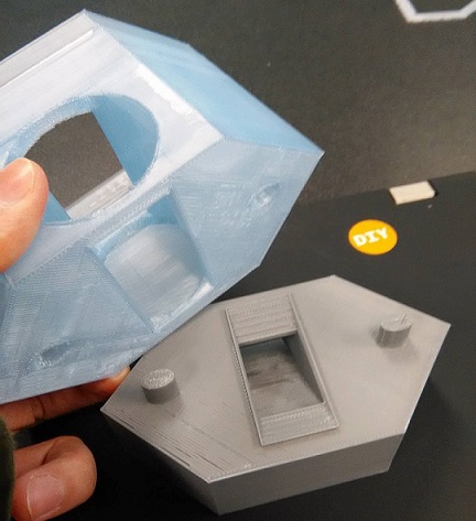
Was based off of this design we found on Thingiverse.
We printed some of the parts from the public library’s 3D printer, which unfortunately has a strict two-hour per day 3D printing limit. The library had a Makerbot Replicator 2, and the preview of a standard quality tank for the dispenser on Makerbot’s desktop predicted over seven hours… so we simply scaled the prints along the y-axis by about 60% if I remember correctly. We also had to reduce print quality significantly to speed up the print time. I remember setting the infill to around 3%, haha. This wasn’t a precision device so I wasn’t too concerned. I also skimped out on the rafts. One of the library employees insisted on me using a raft for the tank as she was worried the print wouldn’t adhere, so I flipped the tank upside down and printed it with a significantly smaller raft. Should it have printed a raft for the full bottom it would have taken ages. I set the printing quality to “Low” on the Makerbot desktop client. That’s all I can remember off of the top of my head. I hope those tips help you if you, too, are subjected to this oppressive two hour time limit at your local public 3D printer.
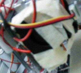
We used an IR break beam mechanism to tell when each pill was dispensed. Well, each Skittle. We used Skittles. But I’m just going to call them “pills” for the rest of this post. We made holes into each side of the dispenser base where the pills would have to pass. You can see where the IR emitter and receiver have been fed into the sides of the pathway here:
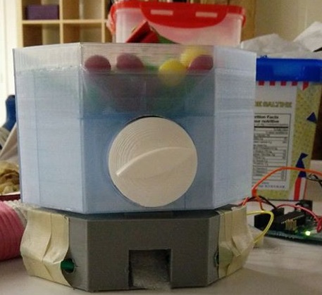
Yes, that is masking tape. Sorry, we didn’t have anything better around.
Here’s a schematic of the hardware we used:
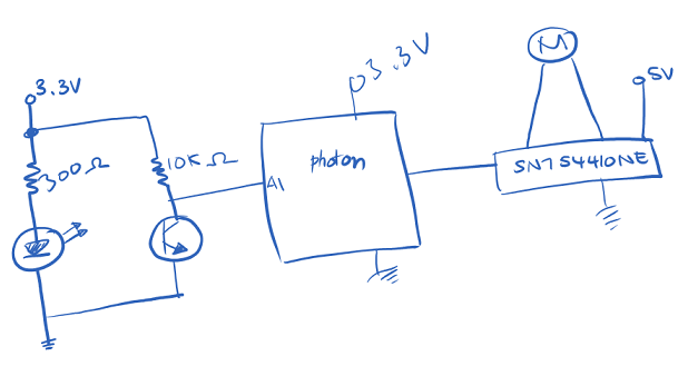
What we messed up on is we didn’t have a good mechanism for the motor to smoothly turn the crank(missing from the photo) effectively. Also the crank didn’t ensure that only one pill was dispensed at a time - skittles sometimes came out in in triplets and would clog the runway. Oh well, that’s what hackathons are for - learning from design you made way too fast. We didn’t really have time to customize a design to 3D model right there and then once we realized this. This was our first hackathon ever, so we didn’t really beat ourselves up over it.
More interesting might be the IoT experience with the Photon, so let’s focus on that for the rest of the post.
Spark Photon has an app (for both IOS and Android), which you can use to connect your spark photon to your wifi network. Sometimes on Windows, I found, this didn’t work and you had to use the command line interface. Once your Photon is connected, you can get to developing.
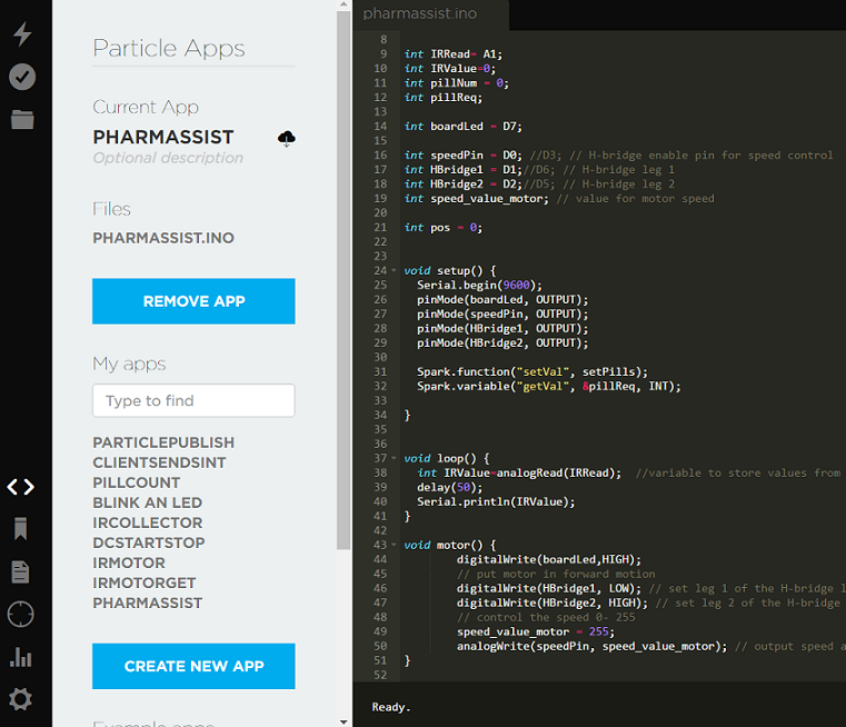
Photon has a web IDE which is pretty handy. It has a very intuitive and easy to use user interface. I felt paranoid about having my files saved only on the web IDE though, so I usually saved my .ino files on Git every once in a while anyways. Photon’s advertising is true to itself in that it is indeed very much like an Arduino experience. As you can see below, I pretty much just coded exactly as if I was writing for Arduino. The only added complexity is Spark Variables and Spark Functions:
I think the only gotcha was trying to use Angular JS with the photon on the client side. This tripped me up a bit, as I couldn’t find many people who had done this online. There was only one part that needed to integrate any code for the Spark photon in anyways, though. This was the one input field for the number of pills to dispense, and the button to tell the photon to dispense pills. You can see the GET and POST request for it here:
//GET
$scope.getSparkValue = function(){
        $http({
            method: 'GET',
            url: "https://api.spark.io/v1/devices/" + deviceID + "/" + getFunc + "/?access_token=" + accessToken,
        })
        .success(function(data) {
                document.getElementById("gotPos").innerHTML = data;
                console.log("get success! data retrieved: " + data);
        })
        .error(function(data, status, headers, config) {
            console.log("get didn't work");
        });
}


$scope.setValue = function () {

    console.log("got to setValue");
    var newValue = document.getElementById('refillNum').value;
    console.log("newValue as of setValue: " + newValue);

        $http({
            method: 'POST',
            url: "https://api.spark.io/v1/devices/" + deviceID + "/" + setFunc + "/?access_token=" + accessToken,
            data: $.param({args: newValue}),
            headers: {'Content-Type': 'application/x-www-form-urlencoded'}
        })
        .success(function(data, status, headers, config) {
            //document.getElementById("gotPos").innerHTML = data;
            console.log("json sent! data sent was: " + data);
        })
        .error(function(data, status, headers, config) {
            console.log("set didn't work");
        });
}

});
You can also just do a call to the Spark API through Jquery, if you’re not using Angular for the rest of your client.
Actually wait, one more gotcha. Spark photon, the last time I tried, does not work on WPA2 enterprise wifi. But other than that I thought it was fairly good.
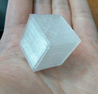
Making the printer was pretty fun, but after printing a few calibration cubes to reassure myself, it sort of sat around for a bit. I printed a couple of guitar picks for friends, but those are flat, easy prints.
After finishing the calibration cube, for the first time ever I had access to a 3D printer. All I had ever seen prior was the glamorous, perfectly calibrated and gorgeous models the online 3D printing hype tries to advertise, so printing failures this time ‘round taught me a few things.
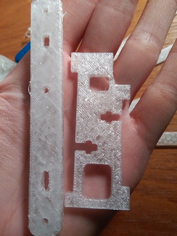
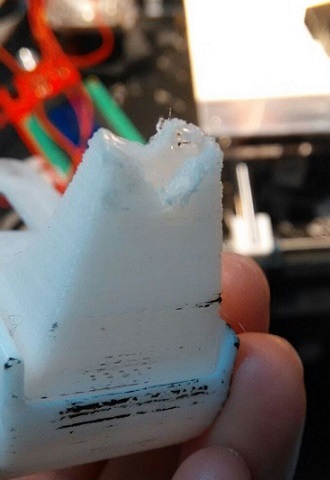
I found out as I started printing a larger variety of items that different types of objects might require attention and tweaking. Another thing I learned is how much of a difference the fan makes. It really makes a difference in terms of precision. I was printing some parts for a 3D printed version of the MeArm,
and the parts I printed without the fan were not very usable. Without the fan blowing the filament didn’t dry quickly enough as it was laid down, so the holes for screws and joints weren’t big enough. Filament would droop into them during the print. I’m not sure how clearly you can see the difference in thise pictures, but here’s a piece printed without the fan on (left) and one with the fan on (right):
I’m wondering if I should bother printing the rest of the MeArm, or just replace a few of the wooden parts I alerady have for it - I haven’t thought of anything ultra cool and useful I would want to do with it. 3D printing is a pretty slow process, and since I bought a very cheap extruder (I actually broke the original extruder at one point, bought another to replace it haha) it actually leaks melted PLA as I print, so sometimes I have to supervise it. If it leaks too much, melted PLA will droop down and interfere with the print. I’d say it’s a good idea to invest in a high quality extruder if you are planning to 3D print a lot.
A good friend of mine is making a home made motor right now, so she’s asked me to print some gears for her. She’s actually designing them herself on AutoCad, so in the meantime we’ve been printing small prototypes.
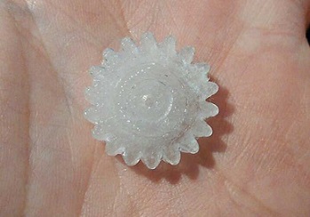
We’ve gotten the dimensions mixed up a few times. Slic3r gives dimensions in millimeters, but we didn’t know that at first and I hadn’t really paid attention to it prior, so this is what the first gear ended up printing as:

One print that gave me some trouble was the gameboy. A friend (the same one, she likes to make a lot of things) asked me to print a shell for a DIY gameboy she was making. Here’s a situation in which turning the fan off for a part of the print was actually a good idea:
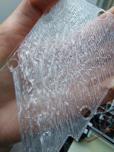
I was printing the bottom the gameboy shell here. What was happening here was that the infill for the bottom was printing at a slow speed, and the filament was drying as it was being laid down. It was drying slowly enough so that it would drop low enough to stick to the lines of infill that had been set down right before it, but fast enough so that it was drying before it had completely fallen onto the platform. This would cause the piece to print sort of mid-air, if that makes sense. It was forming elevated ripples, as shown in the picture above. I fixed this in another round of printing by speeding up the infill printing speed, then turning off the fan for at least the first layer of infill. This made it harder for the PLA to dry quickly.
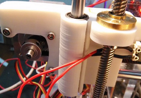
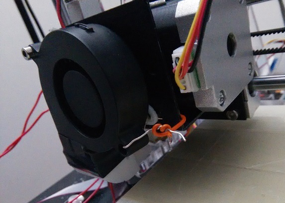
At one point the fan was positioned a bit too low, such that it would scrape and interfere with the print. Sometimes the fan shroud would actually get melted by hitting the extruder and touching the hot PLA:
Part of the problem was that the fan holder provided with the kit didn’t actually line up with the holes on the motor bracket, so it was just dangling from one nut and bolt through a hole at the top left corner of the motor bracket. Another was that it was too low after replacing the extruder with one that had a shorter barrel than the previous one.
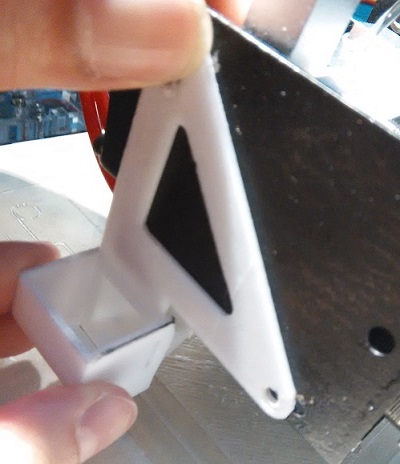
I tried looking for another fan holder + shroud combination to print on Thingiverse, but since this isn’t a standard kit I had a lot of trouble finding one that matched the setup and dimensions of this particular fan-motor-bracket-extruder mechanism. I would really liked to have custom designed one, but I don’t have enough space on my personal laptop for AutoCad (Plus it’s $$$). So for a while I simply scotch taped the fan to a higher position:
Don’t judge, I didn’t really have anything around for a proper quick fix, and am on student budget everything :’(…
Eventually I did a sort of better fix. Seeing as the fan holder provided was definitely 3D printed I figured it was made of PLA or ABS and could be melted. So I soldered a bigger hole into the fan holder so it could be repositioned higher (I don’t have a drill or access to one), then filled up the excess space at the top of the hole by melting PLA into it with the printer. The blob of PLA didn’t allow for enough space for the nut and bolt to reach through the fan, holder, and bracket anymore, so I ended up just sanding it down until it was level once again.
An acquaintance of mine bought 3D printer parts to make a DIY 3D printer. He quickly grew tired of it, however, and after finishing the initial assembly didn’t really feel like working on it anymore. Finding 3D printing fairly fascinating, I took upon the task of carrying on from that point.
I’m wondering if I should call it a “kit”, because I don’t think it was one of those standard DIY 3D printer kits, like the ones I would see people talking about on the open-source DIY 3D printer forums. The parts came in a plain brown box with writing in Chinese on the sides and was taped shut with duct tape. It also didn’t come with the right size of screws for the metal heatbed. Apparently it was bought for about $400 or $450 in cash from someone running a shop in a storage unit.
I wonder if it was supposed to be a comprehensive kit. I think the seller actually made this 3D printer kit himself - there was an acrylic frame for the printer, but some of the parts seemed to definitely be printed by another 3D printer:
The lines along this part definitely look 3D printed, for example.
I couldn’t find tutorials online which seemed to have the exact same combination of types of parts. This one used an MK8 J-head extruder, but I struggled to figure out the details of the stepper motor being used. I believe it was manufactured in China, and I remember having trouble finding a datasheet for it. I ended up guessing at some values when doing some calculations when calibrating, then tweaking with the values till it worked.
The fan holder and nozzle didn’t actually line up with the parts it was supposed to screw onto :(. The second hole in the holder wouldn’t reach. So it ended up just having to dangle from the top, supported by one screw and nut. The fan holder and nozzle was 3D-printed no doubt. You can see both the layers and infill pattern (maybe not very clearly in this badly taken photo):
Eventually I used a wire to twist tie the second hole of the fan to the structure, to keep it stable while printing:
Advanced technology, I know. It made me feel like one of these memes

Note from my 2017 self: As I look over this old post and remember the time I was making this, I sorta shake my head. Just keep in mind that I was making this back with little to no proper tools available… Long story short, I was in Toronto and in a place I didn’t plan on staying for very long, so I didn’t want to invest in tools or equipment either, since I’d be leaving soon anyway. Anyhow looks like I did my best with what I had… sweats
Anyhow, the acrylic frame had an “i3” engraved in it, so I’m assuming the kit was meant to be some hybrid of the Prusa i3 family. Unfortunately it didn’t seem to correspond perfectly for any of the online tutorials on Prusas, but parts of the tutorials were applicable at times. The seller had provided some PDF files for assembling the printer.
I don’t mean to complain about the seller or anything. (I also didn’t even pay for the thing, so what right do I have to be complaining, haha.) Later I went down to him to pick up some more PTFE tubing for the hot end, and he gave me some extra for free and was an all around jolly man. Apparently he provides free support and help if you’re a customer, but his place was pretty far so I preferred to simply figure things out on my own.
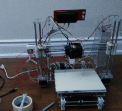
Here is a picture of the printer assembled, but still unprogrammed:
I got used to continually taking apart the fan-extruder-stepper motor mechanism to unclog the extruder. For anyone else considering a 3D printer, after this experience I’d say the higher price of a fully metal hot end (vs a hot end with PTFE tubing) is definitely worth it. Maybe it’d clog less. More importantly though, if you ever overheat the heating block and shoot pass the glassing point of the PTFE tubing, then that PTFE tube will be unusable, and you’ll have to replace it, which can be a bit annoying.
Every time you take apart the extruder to replace PTFE, for example, you have to readjust the z-switch and heat bed height to have the starting height of the printing be not too high and not too low. The hot end of the extruder must be just above, but not touching the heat bed. Just enough so that you can pull a piece of paper between the two and have it be taut.
The board the printer used was an Arduino Mega and RAMPS. Well, not an official one - some duplicate or replica of one, but it is fully functional so I’m not complaining. There are open source firmwares for Prusa printers online, and I tried using some. None of them fit the odd hybrid that which was the printer breed I was working with, so I set to changing and customizing the firmware to fit the particular combination of parts at hand. I tried two or three different versions of Marlin firmware as I had seen some Instructables using it. Unfortunately the custom tweaks in the tutorials I found seemed to be nothing near what this printer needed to function, so I set out to manually experiment and calibrate. In the end I ended up basing my firmware off of Sprinter firmware. I found the Triffid Hunter’s Calibration Guide especially useful, if any of you are on the eye out for one.
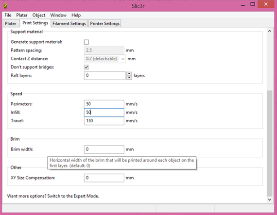
The seller provided a program for controlling the printer on USB, but it was in Chinese, which I don’t understand. So I looked up open source software and looked into making it work with the hardware. At first I tried Pronterface, but I forget why I abandoned it. Anyhow in the end for reasons I don’t remember I decided Repetier Host was the way to go. For generating G-code I like to use Slic3r (not the Slic3r built in with Repetier Host. I downloaded the separate Slic3r application, as I find it has more options and customization available).
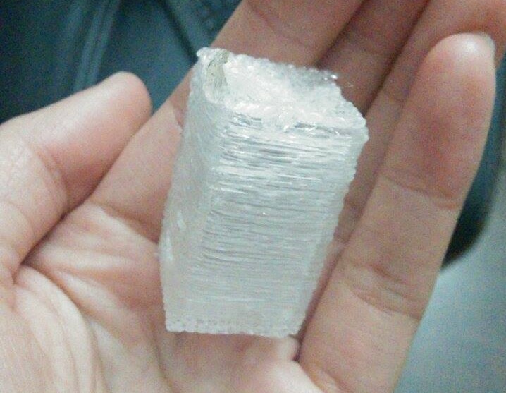
Here is an early attempt at trying to print with even dimensions. This was me trying to print a calibration cube, but it turned out to be the Tower of Babel:
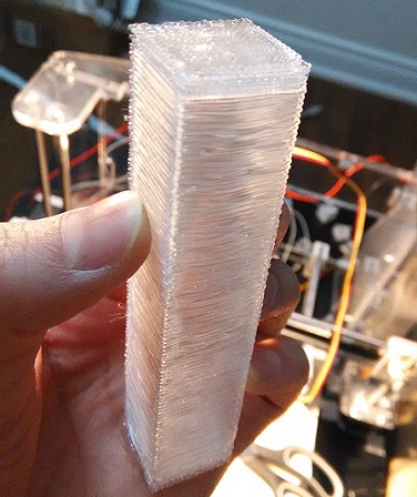
Evidently one of the problems above was that the z-step value was too high. If you look closely at each layer you can see that they slightly droop down. But progress was slowly made:
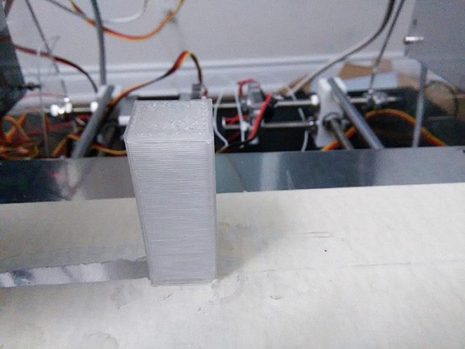
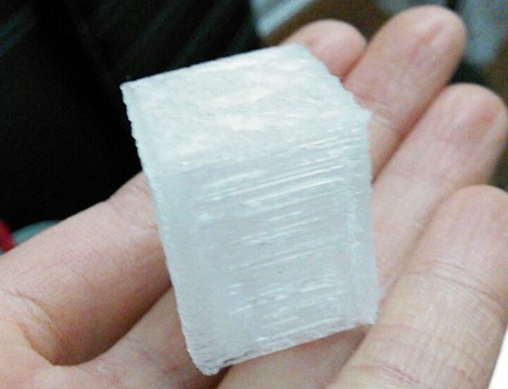
Note the awful build quality on some of those though. If the z-step is too low, the layers will squish together and look ugly. Build quality can also be affected by the extrusion values in the G-code of the object you are printing. This was the first calibration cube that actually came out as, well, a cube:
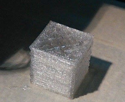
The cube was extremely brittle and actually broke when I pried it off of the heat bed. (That might have be my fault for being impatient and violently ripping it off though.) Anyhow, this fragile cube was printed with G-code generated by Cura. I generated the G-code using the same .stl file except with Slic3r, and found the build quality significantly improved:
Finally, a properly printed calibration cube! I can’t tell you how happy I was about this. I was curious as to why the Slic3r cube and Cura cube turned out so differently, so I pulled out the G-code to inspect. Turns out the default extrusion factor on Cura is smaller than Slic3r’s default value. I could have simply changed this in Cura’s settings instead of switching to Slic3r, but oh well.
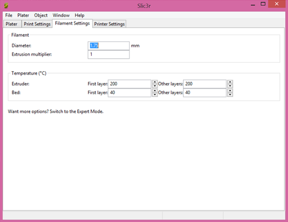
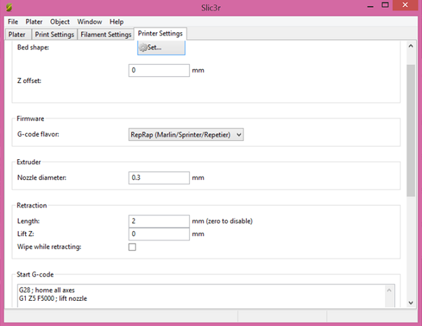
Anyhow, here are the Slic3r settings I like to use, in case anyone was wondering. Moreso for myself to go back and reference if I ever need to, haha.
Before I end this post I’d just like to say that this tape is excellent for getting your print to stick to the heat bed, if you are having any trouble with that:
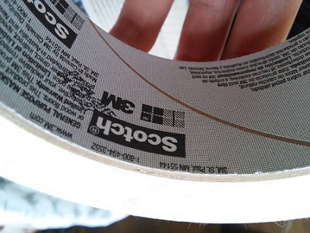
Of course, you can try increasing the heat bed and extruder temperature as well.
I ordered a wooden Mearm a long time ago off of Ebay for fun. I forget which shop exactly I ordered it from on Ebay, but I after shipping and handling I think it came to about $50 CAD. The parts were laser cut wood, but unfortunately didn’t come with any motors. Mearm is a low cost DIY robot arm for hobbyists, created by Hackaday, I think. remember it being advertised as a “kit” so I wish they had mentioned that motors were not included…Oh well. I ordered 9g micro servos motors off of Ebay separately.
After the motors arrived I assembled the robot parts right away, which was a pretty straightforward process. A CD with pdf instructions came with it, though you could always just Google Mearm instructions.
Adafruit has a nice servos motor library for Arduino. I tested a single micro servos with it first to get the hang of it, then modified the code to fit in four servoses, made sure they could be controlled with potentiometers, then hooked up ther servoses in the robot arm.
Later I also bought an ADXL345 accelerometer, so I could control the servos motors was controlled by the tilt of the accelerometer.
The servos motors were pretty weak for the weight of the robot arm. It would move really slowly, or shake and struggle as it tried to lift its heavy head. Eventually one of the motors burned out, and I stopped trying to play around with it. I’m not sure if this was because I bought really cheap motors (they were like $2 each), or because the wood was too heavy… I saw a bunch of metal Mearms on Ebay… I wonder if those are mobile at all!
Whether it be my cheap micro servos motors or the weight of the wood, I’d probably recommend either buying the acrylic Mearm parts from Hackaday, or 3D printing your own parts and setting the infill setting as low as possible. These parts don’t need THAT much precision, so long as they can still fit together. (And if you’re off they’re a good size for simply sanding down anything too big.)